Guide to Ionic Contamination in Electronics
Ionic contamination is one of the leading causes of field failures in electronic assemblies, producing electrochemical migration, corrosion, and degraded dielectric performance. ZESTRON, a global leader in precision cleaning with over 30 years of experience, recommends disciplined contamination control to improve yield and reliability across more than 2,500 customers.
Key takeaways
-
Ionic residues cause electrochemical migration and corrosion.
-
Effective removal requires process-specific cleaning, validation, and materials control.
-
ZESTRON provides cleaning chemistries, process support, and analytical services for verification.
This summarizes methods, acceptable limits, testing techniques, and reliability implications for high performance electronics. Examples and case studies show remediation best practices for fabs and contract manufacturers from ZESTRON today.

Understanding ionic contamination
What is ionic contamination?
Residual ions are ionic residues left on the electronic assembly after soldering, handling cleaning. They are important because in the presence of moisture, they can contribute to electrical leakage, corrosion, dendrite growth, shorts etc.
Ionic contamination consists of soluble ionic residues left on printed circuit boards and components after soldering, handling, or process steps. Common ions include sodium, chloride, potassium, sulfates, and organic ionic species from flux residues. Residues are electrically conductive when hydrated, enabling electrochemical migration and localized corrosion under bias. Levels are typically measured as micrograms of sodium chloride per square centimeter, or by total ionic contamination equivalents. Even small ppm concentrations at critical sites can initiate failure in high density assemblies.
What are Conductive pathways?
Copper PCB traces are conductive paths that provide electrical conductivity between pads. They usually are etched onto the surface layers or embedded within the layers of a PCB. They are protected from corrosion by the solder mask, and they take the solder mask’s color.
What is Moisture activation?
Moisture activation is a phenomenon that occurs when hygroscopic flux residues on a PCB absorb moisture from the surrounding environment increasing surface conductivity on the PCB and could trigger leakage current, corrosion, or electrochemical migration failures.
Sources of ionic contamination
Sources are process steps, materials, and environment. Typical contributors include rosin and no-clean flux residues, solder pastes, fingerprints, detergents, process water impurities, packaging residues, and solder mask outgassing. Contamination can also come from board storage, assembly rework, and fixtures used during manufacturing. Particularly in high temperature lead free processes, flux activators decompose and leave inorganic salts that are highly hygroscopic and aggressive toward copper and solder. Operator hygiene and solvent recycling practices also influence final ionic load.
 Impact on electronic assemblies
Ionic residues lower interfacial resistivity and create paths for dendritic growth when moisture and electric fields are present. Failures include intermittent shorts, leakage currents, increased dielectric loss, and accelerated corrosion under solder joints and component leads. The effect is amplified in miniaturized, high density, or high voltage assemblies used in aerospace, medical, and power electronics. ZESTRON data show that assemblies cleaned to below 0.5 microgram NaCl/cm2 exhibit markedly lower failure rates in accelerated humidity tests. Therefore, cleanliness targets must match customer reliability requirements rather than a single universal number.
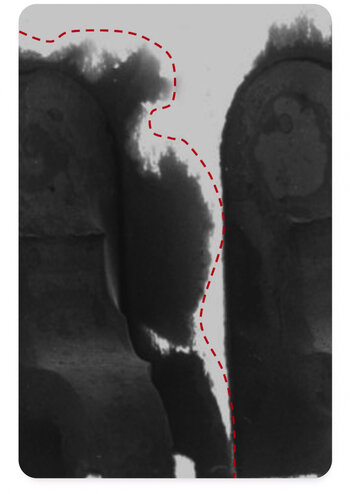
A dendrite is a metal crystal that forms as metal dissolves at an anode and electro deposited at cathode. The electro deposited metal takes the form of a metal crystal. Electrochemical Migration (ECM) results in dendrite growth on the board surface that causes signal disruption, permanent electrical failure and/or loss of assembly function. For ECM to occur, flux is not a requirement but influencing factor. The 3 main factors involved in ECM are humidity, applied voltage and alloys that can electrochemically migrate.
Corrosion occurs when moisture or leftover ionic residue on the board reacts with metal traces and components on the PCB. It appears like rusty buildup that can create shorts and damage the electronic device.
Leakage current is unwanted flow of current between the pad, traces or vias. High leakage current in PCBs is mainly caused by moisture absorption and presence of contamination like dust, flux residues etc. Leakage current can disrupt signals, reduce insulation resistance and lead to failures such as ECM and corrosion.
How do Dendrites occur and affect performance?
Dendrite is a metal crystal that forms as metal dissolves at an anode and electro deposited at cathode. The electro deposited metal takes the form of a metal crystal. Electro chemical Migration (ECM) results in dendrite growth on the board surface that causes signal disruption, permanent electrical failure and/or loss of assembly function. For ECM to occur, flux is not a requirement but influencing factor. The 3 main factors involved in ECM are humidity, applied voltage and alloys that can electrochemically migrate.
What happens with Leakage current and how does it affect performance?
Leakage current is unwanted flow of current between the pad, traces or vias. High leakage current in PCBs is mainly caused by moisture absorption and presence of contamination like dust, flux residues etc. Leakage current can disrupt signals, reduce insulation resistance and lead to failures such as ECM and corrosion.
How does Corrosion occur and affect performance?
Corrosion occurs when moisture or leftover ionic residue on the board reacts with metal traces and components on the PCB. It appears like rusty buildup that can create shorts and damage the electronic device.
What causes Intermittent failures?
Intermittent failures may arise due to ionic residues (from insufficient cleaning), ECM, PCB quality defects and mechanical and physical stress experienced by the components (cold solder joints, weak component connections, voids etc.)

your product requirementsRemoving ionic contamination
Cleaning methods overview
Effective removal combines chemistry, mechanical action, and process control. Selection depends on residue type, board density, component sensitivity, and production throughput. The main approaches are aqueous cleaning, solvent cleaning, ultrasonic assisted processes, CO2 or microemulsion methods, and manual cleaning for rework. Process selection must consider materials compatibility, cycle time, total cost of ownership, and environmental rules. Inline cleaning integrated into assembly lines reduces handling and throughput penalties, but requires robust rinse and wastewater treatment.
Aqueous cleaning techniques
Aqueous cleaning uses water based chemistries to dissolve ionic residues and organic flux by-products. Modern aqueous systems combine surfactants, chelators, and pH modifiers to target specific contaminants. Spray in air, spray under immersion, and cascade systems are selected based on board geometry and throughput. ZESTRON provides formulated chemistries and process control tools to optimize cycles and reduce cycle time without compromising cleanliness. Control of wash water conductivity and replenishment chemistry is critical. Closed-loop systems with ion exchange and filtration maintain chemistry and minimize disposal costs.
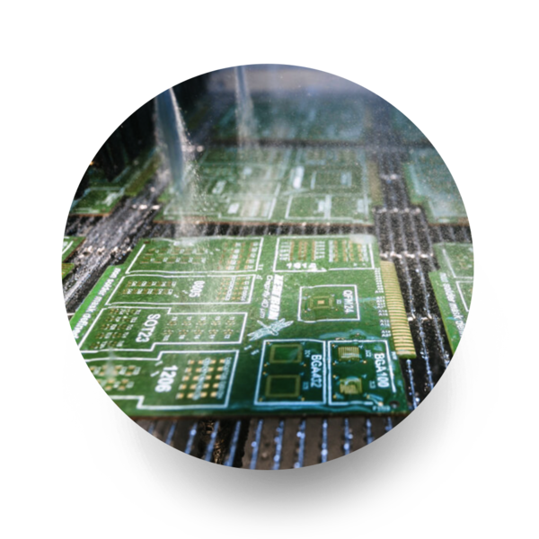
Spray In Air
Uses high-pressure spray nozzles above the cleaning chamber to remove flux residues and contamination from assemblies.
- High spray pressure
- Fast cleaning cycle
- Strong residue removal
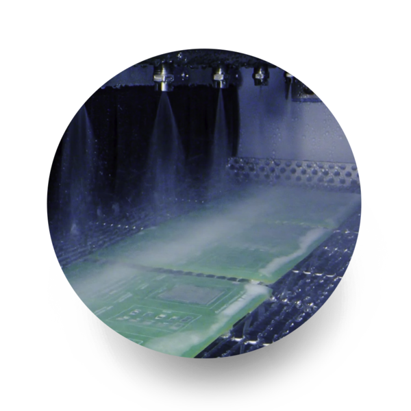
Spray Under Immersion
S.U.I. combines submerged cleaning with spray action to improve penetration under low standoff components and tight spaces.
- Better under components
- Deep gap penetration
- Enhanced coverage
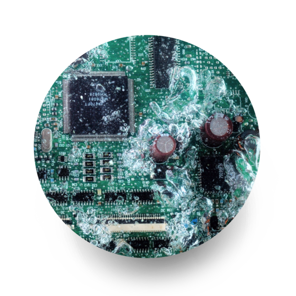
Cascade System
Uses multiple rinse stages where cleaner and rinse water flow in sequence for improved contamination removal and lower chemical use.
- Multiple rinse stages
- Lower chemistry usage
- Improved rinse quality
ZESTRON supports complianceSolvent cleaning strategies
Solvent cleaning is effective for removing polar and nonpolar residues, especially during selective spot cleaning or when water is incompatible with components. Hydrocarbon and oxygenated solvents, plus engineered mixtures, are used according to flammability and environmental rules. ZESTRON solvent products include low residue options and process guidance for solvent recovery and safety. Environmental regulations favor low VOC and non-flammable solvents. Solvent selection often balances solvency, evaporation rate, and safety; ZESTRON supports compliance through solvent lifecycle programs.


ZESTRON supports complianceUltrasonic cleaning systems
Ultrasonic cavitation adds mechanical agitation to improve removal of stubborn residues and undercomponent soils. Frequency, power density, and transducer placement must be tuned to avoid component damage while maximizing cleaning. Ensure that fixtures secure assemblies to avoid resonant damage, and that degas cycles remove dissolved gases which reduce cavitation effectiveness.
Validation & Testing
Validation demonstrates that a cleaning process reduces ionic contamination to acceptable levels and is repeatable. Common steps include process design, residue identification, trial runs, ROSE or ion chromatography verification, and ongoing monitoring. Statistical process control and trend analysis turn sporadic test data into actionable indicators. Include first article inspection, periodic in-line ROSE checks, and quarterly lab based ion chromatography for a robust program.
Acceptable ionic contamination levels
Industry standards and guidelines
Industry guidance comes from IPC, JEDEC, and product specific specifications. IPC TM 650 methods and IPC J STD 001 address flux residue classification and cleanliness test methods. JEDEC JESD22 includes environmental stresses that reveal contamination related failures. ZESTRON whitepapers recommend setting cleanliness targets based on customer requirements, product application, and accelerated test data rather than a single industry number. Many OEMs now issue their own contamination thresholds tied to accelerated testing such as HAST or biased humidity. Suppliers should capture test matrices that replicate field stressors.
Surface Insulation Resistance (SIR) Testing
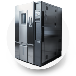
SIR testing is an industry way of assessing the potential of a board to fail through corrosion and other processes associated with ionic contamination. It’s performed at different temp and humidity levels. PCBS or test comb structures are placed in controlled environment and exposed to different test conditions. Parameters that could be varied are temperature, relative humidity and duration of the test. Test duration could be anywhere between 168hrs to upto 1000hrs or more. At ZESTRON, we use Gen3 Systems AutoSIR2 / ESPEC PSL-2J Climatic Chamber for SIR testing.
Rose Testing
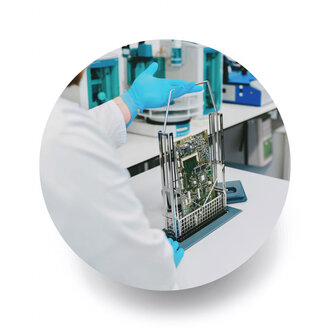
The ROSE (resistivity of solvent extract) test, is used as process control tool to detect the presence of bulk ionics. The test is performed using an Ionic contamination testing unit that detects total ionic contamination but doesn’t identify specific ions present. The results are reported as bulk ions present on PCB per square in. At ZESTRON, we have Aqueous Technologies Zero Ion Tester and Gen 3 CM33+ Ionic Contamination Tester for ROSE testing. An effective contamination control program should define clear sampling plans, including board count, test frequency, surface area evaluated, acceptance limits, and statistical confidence levels. Portable ROSE systems are especially useful for line-side verification.

Ion Chromatography Testing
Ion chromatography test method identifies and quantifies different ionic species that could be present on the board surface. It quantifies the amount of cations, anions and weak organic acids present on the board. Ultimately, cleanliness testing through ion chromatography enables manufacturers to confidently go to market with the highest quality products. It is conducted as per IPC TM-650 2.3.23b. At ZESTRON, we use Thermo Fisher Dionex Integrion for IC testing. Ion chromatography gives species specific quantification of sodium, potassium, chloride, sulfate, and other ions and is the definitive laboratory method for failure analysis. Best practice is to use ROSE for rapid process control and reserve ion chromatography for failure analysis and contractually agreed acceptance testing. Correlate ROSE NaCl equivalents with IC species to build meaningful alarms.

Visual Inspection Testing
Visual inspection is the first step in verifying the cleanliness level of boards post the wash step. It is important to ensure the pcb looks visually clean prior to using the board for any subsequent analytical testing methods. If the board appears dirty during inspection, it will help customer go back to his process and give him a chance to optimize the wash settings to ensure they meet visual cleanliness requirements. At ZESTRON, we use Keyence VHX-7000 microscope for visual inspection.
Acceptable Levels by Industry
What are the most current IPC standards we follow?
IPC-TM-650 standard based on J-STD-001 Rev G for ROSE testing
IPC TM 650, Method 2.3.28. for Ion Chromatography testing per IPC TM650, Method 2.6.3.7 for SIR testing
Ionic contamination and reliability in electronics
Effects on high performance electronics
High performance systems such as aerospace, automotive ADAS, medical implants, and power conversion have tight cleanliness tolerances because failures can be catastrophic and costly. Ionic residues under bias and humidity drive electrochemical migration, dendritic growth, and leakage paths that reduce mean time between failures and can invalidate warranty. ZESTRON testing shows assemblies cleaned to stringent targets pass accelerated humidity and bias testing with far fewer anomalies, and this influences supplier selection by OEMs. Design for cleanliness includes specifying no-clean fluxes that leave benign residues, minimizing solder paste voids, and designing conformal coating processes that encapsulate any remaining ionic species. Quantify risk by running biased humidity tests, thermal cycling with moisture soak, and real time field data. Use accelerated test correlations to set production acceptance criteria.
 Common contamination issues
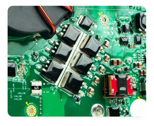
Common problems include ionic hotspots under BGAs, flux residue pooling near connectors, nozzle contamination in pick and place, and reflow machine carryover. Conformal coating can trap ions unless cleaning precedes coating. Supply chain issues such as contaminated PCB laminates or adhesive tapes also introduce unexpected ionic loads. Connector pitch reduction and shielded enclosures complicate cleaning access, making early design reviews and test coupons important.
Prevention and mitigation strategies
Mitigation blends process control, material selection, cleaning, and inspection. Actions include controlling flux type and volume, specifying low ionic raw materials, instituting inline cleaning, and validating with ROSE and ion chromatography. Document materials, require certificates of conformance for fluxes and adhesives, and include cleaners and test methods in supplier quality agreements.
Get Educated On Ionic Contamination
Can one Effectively Clean Under Low Stand Off Components?-White Paper
The emergence of smaller components is placing significantly more strain on all cleaning requirements. Chip components are currently placing the highest demand on removability as gaps are being reduced to less than 1 MIL.
Moisture and Material-Induced Failure Mechanisms in Power Electronics -White Paper
Corrosion on electronic and power electronic devices is one of the major effects, which negatively affect the reliability of the respective device. The ZESTRON experience from over many years of failure analysis and risk assessment in this area clearly reveal that in power electrics especially the anodic migration phenomenon (AMP) is the corrosion mechanism most often found under high voltage conditions in combination with high humidity load.
Conclusion: The importance of ionic contamination control
Controlling ionic contamination is not optional for manufacturers of high reliability electronics. It reduces field failures, warranty costs, and rework, while increasing customer confidence and regulatory compliance. Implement a structured program: characterize residues, choose a validated cleaning method, monitor with ROSE for process control and ion chromatography for lab verification, and train personnel on material and process control. Partnering with a specialist such as ZESTRON brings formulated chemistries, process engineering, and global technical centers that accelerate qualification and reduce operational risk. For high performance applications, set conservative targets, use localized testing for hotspots, and verify with accelerated environmental stress tests to ensure long term reliability. ZESTRON's analytical services and validated cleaning processes help OEMs and CMOs meet these targets, protecting brand reputation and reducing lifecycle costs. Contact ZESTRON's technical center network for on-site audits, ROSE mapping, and tailored cleaning validations to meet 2026 reliability demands. Start with a quick cleanliness audit today. Get started.
FAQ
Remove ions using a matched cleaning process: identify residue, select chemistry (aqueous or solvent), choose mechanical action (spray, ultrasonic), run validated cycles, and verify by ROSE or ion chromatography. ZESTRON offers full process support.
Acceptable levels depend on application. Common industrial targets range from 0.1 to 1.6 microgram NaCl/cm2; ZESTRON recommends defining targets based on accelerated testing and customer risk rather than a single universal limit.
ROSE is quick and suited for inline process control, reporting NaCl equivalent. Ion chromatography is slower but species specific and essential for root cause analysis. Use ROSE for monitoring and IC for failure investigation.